Tuesday, 14 December 2010

Fabrication 4 (fins)

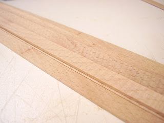
Assembling the walls of the model has proved one of the most time consuming processes of the entire build. I made a jig to help me cut the beech strips to length which, has actually proved to only be helpful in marking out the point on each piece where it needs to be cut. I had intended to saw them individually with a joiners saw but found that a saw tares up the fibres in the wood on the back too much. Because of this I switched to using a pair of wire cutters which, allows me to cut them much faster and more accurately. It also avoids ruining one side of the fin. 

Fin Marking Jig

Fins stuck in place on smallest curve

Fins stuck in place of longest flat curve

After cutting each fin to length I've needed to sand a slight taper on the end to be stuck into the slot on the acrylic curve. Because of the number of layers of paint I sprayed the curves with I've filled in the slots a little more than I should, so they're a little under 1mm wide. This does, however, mean that each fin is a very tight and secure fit.
I'm sticking the fins in place with Areldite Quick Set epoxy adhesive. This sets in approximately 3 minutes (it's supposed to be a 90 second cure). This means I can only stick 5 or 6 fins in place at a time before the Areldite sets. This gives me time to stick the 5 or 6 and then a few minutes to prepare another set ready for when the Areldite has properly cured - 10 minutes is best.

Friday, 3 December 2010

Fabrication 3 (platform and ramp)

To make the ramp/platform of the venue I've chosen to use 3mm acrylic. I made an MDF former box to heat bend the acrylic clotted curve on and which, I will also use to baed the angle of the platform.
SketchUp model of acrylic former box

MDF former box

I heat bent the slotted curve of the platform over the former box and then, using the interior line of that curve as a template, drew around it onto 120gsm white card. I attached the card to a sheet of 3mm acrylic and cut around the template on the bandsaw. After achieving the basic shape as close to the lines as possible, I used the bobbin sander to smooth the interior curves and get a more accurate shape. I then hand sanded the edges top make them smooth enough to adhere to the slotted curve.

Heat bending acrylic curve over MDF former

Heat bending ramp over MDF former

Once I had the platform and acrylic curve bent to shape, I found I needed to put a chamfer on the underside of the base of the ramp to insure it will sit flush on the baseboard. I found the angle that the ramp will sit at, drew a line across the width of it on the underside and, quite simply, sanded away the excess that lay above the line until the new surface met with both the end of the ramp and the drawn line.

Sanding chamfer across underside of the ramp base

Tuesday, 30 November 2010

Baseboard Fabrication 2 (making)

Using the dimensions from the SketchUp model I made, which incorporated the MDF thickness (9mm) into the components, I was able to saw the MDF and assemble the whole thing in less than 2 hours. I made the model to help me find the correct dimensions because I've had serious problems working out side panel lengths in the past when only relying on my ability to calculate them.
As the baseboard is close to a metre square I decided it would be best to include a beam across the middle to support the weight of the model or, at least, prevent the top of from bowing too much. This piece was simply a third side panel tacked and glued into place with wood glue and veneer pins.
I also used filler to solidify the corner joints of the baseboard, something I might find I will regret in the near future as it will get in the way of the feet I intend to put on the box. A rash decision, but hopefully easily rectified.

Baseboard without paved area attached

Underside of baseboard showing supportive beam

Monday, 22 November 2010

Baseboard Fabrication 1 (prep)

Dimensions: 1000mm x 900mm x 62mm
The baseboard I have designed will contain little more than the area of Parliament Square that the venue stands on and a diagonal cut through of the High Street on the north side of the square. The top of the board will stand 62-63mm high (dependent on adhesives and finish). It was originally intended to stand only 60mm but I forgot to allow for the top board representing the square which, is raised above the surface of the road by 2.5mm (representing a rise from road to pavement of 100mm).

SketchUp model of my baseboard. I sketched this design to work out the physical dimensions, making it easier to cut out and assemble.


The area representing the square will be finished in a pale greyish-brown (to show paving slabs/cobbles). I had hoped to laser-etch a cobble texture into the top board but am not able to as the sheet is too large to fit in the laser cutter.
The road surface will be sprayed with either a slightly textured paint or a plain, matte grey which, will represent the tar macadam.
The sides of the board will be clad with a wood veneer. I am, as yet, undecided on which wood I will use but I would like to compliment the colour of the beech I've used for the fins of the venue's walls. I had been thinking along the lines of either a very pale wood - maple, sycamore, birch etc. - or a much darker wood - ebony, walnut, sapele etc. Ebony is unlikely as it's a hard veneer to come across and very expensive. Walnut would compliment the pale, warm and slightly pinkish appearance of the beech very well.

Slotted Curves

The base of the venue - the pieces that hold the wooden fins in place - are proving tricky to fabricate. Working from the architects original drawings, which leave a large amount to the imagination, I drew out new shapes from those included in one of the plan views. The curves work out to be only 5mm x 5mm (high x wide) in 1:40 which, will make them incredibly delicate to work with. The wooden fins will sit in 2mm deep slots that will run all the way along the curves at regular intervals but at varying angles. The fins follow a basic wave shape, starting off at near perpendicular to the outer face and then shaping away from that angle and then back towards it again. The fins also have a staggered lean to them all the way round. The base of each fin lies square to the ground but the tops appear to be square to the parallel sides.
I've chosen to laser cut the curves out of 5mm acrylic, etching (in two passes) the slots and then cutting the curves out in one run.

 Attempt 1 (fail) After doing one etching pass, which took and hour and a half, I ran out of time on the laser. Ed etched locator points in the corners but when we tried to line it up a few days later (when the laser became free again) it didn't etch in to the same points and messed up the sheet of acrylic. I came back the following morning and did it all again with black acrylic. Below are the results. 1.8mm etched slots in a 5mm x 5mm curve. 

 The three etched curves

 Etching

The curves in their entirety

From this point I have sanded the curves smooth, as the sides were grooves from the etched lines. I started with a fine sand paper and then progressed to 320 and then 500 grit wet and dry. I will be spraying them a very dark grey - graphite or charcoal - to match the colour shown in the graphic illustrations from Jonathan Knox.


Wednesday, 3 November 2010

Beech Strips

After sawing the 2mm strips of beech on the bandsaw I then have to sand them down to 1mm. This requires, as I've already said, belt sanding on the flat bed sander and then hand-sanding to a smooth finish.
This is what the strips look like after being sawn:

 After being sanded on the belt sander:

 The hand-finished strips:

As some of the beech I've used is very pale compared to some of the other pieces I feel I should even up the colours a little. Do do this I've been testing wood dyes and waxes on the paler wood to create a match to the darker, slightly redder pieces.

Colour matching:

Colour Matching:
Left: original wood colour
Centre: dilution of red dye mixed with liquid wax
Right: (lower end) diluted red dye with overcoat of liquid wax, (upper end) less diluted red dye, no wax.

From my tests I've found the closest match is the dilution of red dye with an overcoat of liquid wax. I had been intending to give all the strips a coat of wax before assembling the model which, will give the wood a warmer and softer appearance. It should also help prolong the life of the wood and stabilise it, preventing excessive warping from atmospheric moisture fluctuations.

Saturday, 30 October 2010

Materials Research

Beech, the wood I've chosen to use is 's strong hardwood with a fine grain, and is light brown in colour. It is available in a range of thicknesses... a very suitable modelmaking material.' (Dunn. N, 2010, Architectural Modelmaking, Lawrence King Publishing Ltd, London)
I bought a selection of four various sized off-cuts from Columbia Timber for £5 which I hope to be able to make all of the walls of the model with.
I did also research whether it would be possible to buy ready cut strips of beech that would be suitable for the model but found, to my slight astonishment, that it's not available in 1mm thickness. I found a selection of lengths and widths but none available in 1mm x 10mm. The closest I've been able to find online are 0.6mm or 2mm x 10mm x 1000mm strips which, considering the scale I've chosen (1:40), would mean I'd still have to do a lot of sanding to get them to the correct thickness. I could alter the scale to suit the materials available but I think that would be a little lazy, however practical. It would also result in a drastic change in the size of the model. If I were to switch scale from 1:40 to 1:20, allowing me to use 2mm thick strips then the final model would be over 1000mm across… a little too large, in my opinion. 
A few sources of beech strip:

Instead of changing scale, I've taken to sawing various lengths of 10mm wide strips on the bandsaw. I'm using the bandsaw rather than the circular saw because, although the saw marks are more pronounced, I run little risk of losing the strips on a bandsaw. The circular saw has a gap running alongside the blade that is just the right width for thin strips to fall down as soon as they've been cut off the main block.
I'm sawing the strips between 1.5mm and 2mm thick to allow for discrepancies on the surface - saw blade tooth marks. After sawing the strips I need to remove the saw marks and thin them down to 1mm. This is done by sticking them to a piece of MDF, with double-sided tape, and then putting them on the flat-bed belt sander. After I've removed all the saw marks from one side I turn the strips over and repeat the process. I then remove them from the MDF and measure the thickness. I'm aiming for about 1.2mm thick after the first two sanding runs. This allows me to then hand sand them down to exactly 1mm with three grades of paper. I'm using a coarse (120) and medium (240) grit sandpaper and 400 grit wet and dry (without water). This gives a smooth surface ready for any finishes I might need to add.

Wednesday, 20 October 2010

Materials Testing

Beech


Cedar - end grain

Mahogany (imitation)

Maple

Oak (misc)

Teak

White Oak

This is a selection of the hardwoods that I've looked at. I'm trying to find a reasonably pale, tight-grained wood that saws and sands well into narrow pieces.
Of the woods I've tested so far I've found beech and maple to be the most suitable. Beech because its grain is very straight and organised and not overly elaborate. 
Maple seems a suitable choices as well because of its very dense quality and nicely regimented grain structure. Although a little curvier than beech, the grain on maple would probably scale very well because it's not too bitty.
I will, once I find some, also analyse the properties of ash and, if possible, basswood/lime which, is a standard modelmaker's wood.

Monday, 18 October 2010

Sketch Model


Grey Card sketch model of Street Per_Form venue.
This model is primarily to help me gain a greater understanding of what the final design will look like. Because of it's peculiar shape and the drawings being a little difficult to interpret, making a sketch model is the simplest way of grasping the designs strengths and flaws.


Wednesday, 13 October 2010

Street Per_From - Sketch Model

The sketch model of my design is now complete (structure only). I haven't made any of the surrounding buildings to set it into but might do at a later date.
What I've discovered from making this is that there are a lot of the 'domino-tooth' pieces to be made and put in place. It's taken me approximately 3 days to make the maquette, using only grey card and PVA glue. The purpose of the sketch model is primarily to gain a greater understanding of how the structure will look when complete and outline obvious difficulties I might have in its construction.
One of my greatest concerns is actually the shear number of 'domino-teeth' that I'm going to have to make. I'm yet to count them out individually but I should think there are at least 100+, all of varying sizes, angles and slant - all important things to be considered while making them.
Another concern I have is the possibility of using the laser-cutter being gone. I had originally planned to laser cut each piece of the structure's walls but, since I've chosen to make them out of wood, possibly cedar or oak, this is less likely because of the unavoidable scorching from the laser. With that in mind, I think it's now much more likely I'll make them individually using the circular saw and hand-sanding.
Although more time consuming, I think I'll be able to make it as accurately as the laser and avoid ruining the wood.
This might, however, mean the baseboard will require a laser cut outline of small holes for the teeth to slot into at their respective angles - the angles being created by making a two-tier base with the lower board shifting the teeth in one direction or another by being offset from the top surface's holes.
(picture of sketch model to be added)

Thursday, 7 October 2010

Street Per_From

This is the design that I will be creating in model form in the weeks from now leading up to Christmas. It's a complicated-looking thing but, providing I make it well and re-learn how to use Rhino, should look pretty nice as an architectural piece. I'm still trying to decide the scale but seeing as I'm leaning towards using real wood to represent the wooden 'domino-tooth' walls (as I'm calling them), I think a larger scale would suit it best, probably 1:100 or there abouts.
I shall be updating fairly regularly from now on, provided I remember.

Saturday, 2 October 2010

It's nearly upon us

The new term, first of third year, begins on Monday and I'm not ready.
We were given the task this summer of choosing our first project of the year and doing the majority of our preparation research for it before we start back. Well, I haven't done quite enough yet. I picked the subject matter for the project back in June, only a week or two after the end of term, with the intention of getting a head start on it and being ready to start making as soon as I got back to uni. This was a little optimistic of me.
I have the model subject matter, which is good. It's a concept design for a temporary venue at the Edinburgh Fringe Festival. It's designed to stand in the square outside St. Giles Cathedral just off the Royal Mile. It's a contemporary and very sleek design, utilising the space wisely by splitting the area it cordons off into two level by use of a ramp. It's a university piece by freelance designer Jonathan Knox and is named 'Street Per_Form'.
I looked into a few other designs, both architectural and product design-based but chose this piece quite simply because it's an interesting design and would, I think, make a really nice model at the right scale and with the appropriate materials.

Friday, 20 August 2010

News (of sorts)

The architectural model that I've been working on recently is ended, not finished but ended.
I had a meeting with the architect, during which we discussed the progress of the model, which was slow (to put it mildly), and the relevance of it. He informed me that his client, who the model was being made for, was having problems with the neighbour's granting planning permission to develop the whole plot as originally intended. This, as it transpired, meant the model I was making, from the plans he'd given me, wasn't actually going to be of what would eventually get built - if anything does in the end.
Because of that, and what appears to have been a serious misunderstanding about the scale I was making it at (which I discussed previously), he confirmed that the model was no longer needed and that I didn't need to carry on with it.
Needless to say I was a little irked at this news. Although I wasn't particularly enjoying making it, because of the lack of relevant information on the plans I was given and the slightly tawdry subject matter, I would have liked to have finished it, if only for my own satisfaction.
I was paid (only half of what was originally agreed, but paid all the same) on the principle that I'd made roughly half the model. That seemed only fair and I was happy to leave it at that. I was a little annoyed a short while after he'd left, when I realised that I hadn't taken any photos of what I'd done, apart from on my shockingly poor camera phone, which will not be gracing your screens.


All in all this trip back to Bournemouth was a fairly fruitless endeavour. Having spent close to four whole weeks down here I have very little to show for it other than managing to find somewhere to live for September.
It's unlikely I'll post anything else between now and when term starts at university as I'll probably be at home, working on the projects I'd planned to spend my summer doing. Namely, stripping, priming and then re-spraying my old Royal Enfield bicycle frame and, hopefully, fitting a few new parts to it.
You never know though. I might get incredibly bored and go and do something productive, like join Rich at Seamless on work experience for a couple of weeks. But for now, that's it.

Friday, 6 August 2010

So...

I'm currently working on a private commission for architect David Wright. The project was forwarded on to me, rather fortuitously, from a couple of now graduated third year students from my course who couldn't take it on because they'd already found employment.
The commission is a card model of a proposed build in Evening Hills, Poole at a scale of either 1:100 or 1:200. I chose 1:200, thinking it might be a little easier to make at a smaller scale... this has not been the case.
The material was restricted to card - mountboard in particular - which, as lovely as it is to work with, is not great for small models. I've found that the board cuts fairly easily but when the parts one's making are of the size they are, the edges can split or pucker.
If I'm honest, I wish I had better plans to work from. Those that the architect gave me don't have the amount of information I really need to work from. I have several sheets of plans to glean the information from... I have a 1:200 scale, A1 of the full site and neighbouring properties; another 1:200 A2 sheet of the side elevations; and three 1:100 scale A2 sheets of the proposed building's interior layouts (each sheet displaying a different story of the structure).
I've encountered several problems so far: the A1 1:200 site plan has hand-drawn revisions, which are less than accurate. These revisions are shown clearly on the three A2 1:100 floor plans, but are very hard to decipher. Nevertheless, I have committed myself the to project and must have it finished soon. There's been no official deadline set but I'd like to have it finished by August 19th.
I will upload some photos of the finished model. I would put the plans on here but I think that might be illegal as they were given to me in confidence.

Wednesday, 4 August 2010

Here we go again

I'm sure there are literally thousands of you who've been utterly mortified by the disappearance of my previous posts. I'm afraid I couldn't keep it updated regularly enough for me to consider it a worthwhile use of my time. Instead, I've decided to start a fresh.
This new one, of the same amazing name, will be more about the things I do week in week out on in the time leading up to and period of my final year at university (it may continue after I've graduated).
I'm on the very well respected BA (Hons) Modelmaking degree at AUCB (formerly AIB). This degree is considered one of if not the best in the country. It incorporates the various and wide-ranging disciplines of the modelmaking industry and, boasts an impressive record of former graduate successes.
Anyway, this blog will give you an insight into the things I do on the course and in my spare time. It might not be all engrossing, but you might find it a little interesting. I will attempt to keep this one a little more up-to-date than the last one but I'm not guaranteeing anything.